Guide to making a CHIP-8 emulator
A high-level guide to making a CHIP-8 emulator.
Do you want to get into emulator development? A common advice is to start out with CHIP-8. But how do you do that? And why are there so many different, conflicting specifications?
This is a guide for you. It will tell you how to make a CHIP-8 emulator, but it won’t give away the code. It will explain what each part should do, and use some pseudocode at times, but the actual implementation will be up to you.
Along the way I’ll put tips in green boxes, warnings in orange boxes (things to look out for), and trivia (mostly historical) in blue boxes. Like this one:
Everyone calls them “CHIP-8 emulators”, since they’re a common starting point for learning how to develop emulators, but they’re not actually emulators. An emulator emulates physical hardware in software, but CHIP-8 isn’t a piece of hardware. To be pedantic, you’re writing a CHIP-8 interpreter.
If you have any suggestions for this guide, or just want to show off an emulator you’ve made, please leave a comment at the end of the page!
History
CHIP-8 was created by RCA engineer Joe Weisbecker in 1977 for the COSMAC VIP microcomputer. It was intended as a simpler way to make small programs and games for the computer. Instead of using machine language for the VIP’s CDP1802 processor, you could type in hexadecimal instructions (with the VIP’s hex keypad) that resembled machine code, but which were more high-level, and interpreted on the fly by a small program (the CHIP-8 emulator/interpreter).
CHIP-8 soon spread to other computers, like the Finnish Telmac 1800, the Australian DREAM 6800, ETI-660 and MicroBee, and the Canadian ACE VDU.
By 1984 the interest in CHIP-8 petered out. However, in 1990 it had a renaissance on the HP48 graphing calculators with CHIP-48 and the now-famous SUPER-CHIP extension with higher resolution.
With so many different implementations over several decades, there are many inconsistent specifications. I’ll clear those up for you along the way.
Michael J. Bauer, who made the DREAM 6800 computer and its CHIP-8 interpreter in 1978, invented the following backronym for CHIP-8: Compact Hexadecimal Interpretive Programming – 8-bit.
Prerequisites
This is a CHIP-8 tutorial, not a programming tutorial. You should already know some programming before making an emulator, in my opinion, or you’ll have a rough time.
You will also need to have a basic understanding of the binary and hexadecimal number systems; I will write hexadecimal numbers like this: B3. CHIP-8 programs are binary files, and your emulator will need to read these files and operate on the bytes.
You will also need a way to draw graphics to the screen, and read keypresses. Many graphical libraries can do this for you, or you can use something like SDL directly.
Specifications
CHIP-8 has the following components:
- Memory: CHIP-8 has direct access to up to 4 kilobytes of RAM
- Display: 64 x 32 pixels (or 128 x 64 for SUPER-CHIP) monochrome, ie. black or white
- A program counter, often called just “PC”, which points at the current instruction in memory
- One 16-bit index register called “I” which is used to point at locations in memory
- A stack for 16-bit addresses, which is used to call subroutines/functions and return from them
- An 8-bit delay timer which is decremented at a rate of 60 Hz (60 times per second) until it reaches 0
- An 8-bit sound timer which functions like the delay timer, but which also gives off a beeping sound as long as it’s not 0
- 16 8-bit (one byte) general-purpose variable registers numbered
0throughFhexadecimal, ie. 0 through 15 in decimal, calledV0throughVFVFis also used as a flag register; many instructions will set it to either 1 or 0 based on some rule, for example using it as a carry flag
That’s it!
Memory
The memory should be 4 kB (4 kilobytes, ie. 4096 bytes) large. CHIP-8’s index register and program counter can only address 12 bits (conveniently), which is 4096 addresses.
The index register, program counter and stack entries are all actually 16 bits long. In theory, they could increment beyond 4 kB of memory addresses. In practice, no CHIP-8 games do that. The early computers running CHIP-8 usually had less than 4 kB of RAM anyway.
All the memory is RAM and should be considered to be writable. CHIP-8 games can, and do, modify themselves.
CHIP-8 programs you find online as binary files are often called “ROMs”, like game files for video game emulators, but unlike games on console cartridges they were not actually ROM (which means “read-only memory”).
The first CHIP-8 interpreter (on the COSMAC VIP computer) was also located in RAM, from address 000 to 1FF. It would expect a CHIP-8 program to be loaded into memory after it, starting at address 200 (512 in decimal). Although modern interpreters are not in the same memory space, you should do the same to be able to run the old programs; you can just leave the initial space empty, except for the font.
Font
The CHIP-8 emulator should have a built-in font, with sprite data representing the hexadecimal numbers from 0 through F. Each font character should be 4 pixels wide by 5 pixels tall. These font sprites are drawn just like regular sprites (see below).
You should store the font data in memory, because games will draw these characters like regular sprites: They set the index register I to the character’s memory location and then draw it. There’s a special instruction for setting I to a character’s address, so you can choose where to put it. Anywhere in the first 512 bytes (000–1FF) is fine. For some reason, it’s become popular to put it at 050–09F, so you can follow that convention if you want.
The font most people use is represented in bytes like this:
1
2
3
4
5
6
7
8
9
10
11
12
13
14
15
16
0xF0, 0x90, 0x90, 0x90, 0xF0, // 0
0x20, 0x60, 0x20, 0x20, 0x70, // 1
0xF0, 0x10, 0xF0, 0x80, 0xF0, // 2
0xF0, 0x10, 0xF0, 0x10, 0xF0, // 3
0x90, 0x90, 0xF0, 0x10, 0x10, // 4
0xF0, 0x80, 0xF0, 0x10, 0xF0, // 5
0xF0, 0x80, 0xF0, 0x90, 0xF0, // 6
0xF0, 0x10, 0x20, 0x40, 0x40, // 7
0xF0, 0x90, 0xF0, 0x90, 0xF0, // 8
0xF0, 0x90, 0xF0, 0x10, 0xF0, // 9
0xF0, 0x90, 0xF0, 0x90, 0x90, // A
0xE0, 0x90, 0xE0, 0x90, 0xE0, // B
0xF0, 0x80, 0x80, 0x80, 0xF0, // C
0xE0, 0x90, 0x90, 0x90, 0xE0, // D
0xF0, 0x80, 0xF0, 0x80, 0xF0, // E
0xF0, 0x80, 0xF0, 0x80, 0x80  // F
In theory you could design your own font; it’s unlikely that any games rely on the shapes of the characters. Many of the early computer implementations had their own fonts.
Display
The display is 64 pixels wide and 32 pixels tall. Each pixel can be on or off. In other words, each pixel is a boolean value, or a bit.
The early computers used regular TVs as screens, so an “off” pixel was just black, and “on” was white. You can pick other colors.
Original interpreters updated the display at 60 Hz (ie. they had 60 FPS, to use modern terminology). How you do this is up to you, but depending on the framework you use, it might be a good idea to only redraw the screen when your emulator executes an instruction that modifies the display data (there are two), to run faster.
The details of the drawing instruction DXYN are found below, but in short, it is used to draw a “sprite” on the screen. Each sprite consists of 8-bit bytes, where each bit corresponds to a horizontal pixel; sprites are between 1 and 15 bytes tall. They’re drawn to the screen by treating all 0 bits as transparent, and all the 1 bits will “flip” the pixels in the locations of the screen that it’s drawn to. (You might recognize this as logical XOR.)
This method of drawing will inevitable cause some flickering objects; when a sprite is moved, it’s first erased from the screen (by simply drawing it again, flipping all its lit pixels) and then re-drawn in the new position, so it will disappear for a little while, often causing a flickering effect. If you want, you can try to think of ways to mitigate this. For example, pixels that are erased could fade out instead of disappearing completely, giving an old phosphorous CRT-style effect.
Stack
CHIP-8 has a stack (a common “last in, first out” data structure where you can either “push” data to it or “pop” the last piece of data you pushed). You can represent it however you’d like; a stack if your programming language has it, or an array. CHIP-8 uses it to call and return from subroutines (“functions”) and nothing else, so you will be saving addresses there; 16-bit (or really only 12-bit) numbers.
Early interpreters reserved some memory for the stack, and some programs would use that knowledge to operate the stack directly and save stuff there, but you don’t need to do that. You can just use a variable outside the emulated memory.
These original interpreters had limited space on the stack; usually at least 16 two-byte entries. You can limit the stack likewise, or just keep it unlimited. CHIP-8 programs usually don’t nest subroutine calls too much since the stack was so small originally, so it doesn’t really matter (unless you encounter a program with a bug that has an infinite call loop and causes a “stack overflow”).
Timers
There are two separate timer registers: The delay timer and the sound timer. They both work the same way; they’re one byte in size, and as long as their value is above 0, they should be decremented by one 60 times per second (ie. at 60 Hz). This is independent of the speed of the fetch/decode/execute loop below.
The sound timer is special in that it should make the computer “beep” as long as it’s above 0.
Even though it’s called the “delay” timer, your interpreter should run as normal while it’s being decremented (the same goes for the sound timer). The CHIP-8 game will check the value of the timer and delay itself if it wants.
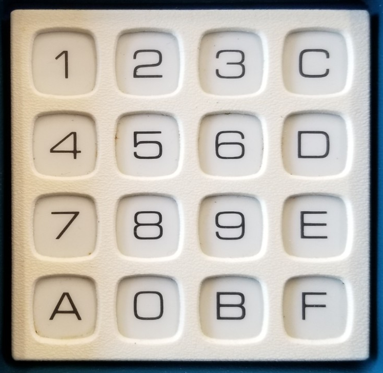
Keypad
The earliest computers that CHIP-8 were used with had hexadecimal keypads. These had 16 keys, labelled 0 through F, and were arranged in a 4x4 grid.
On the original COSMAC VIP, a sound (the same sound as the sound timer uses) would be heard while holding down a key. This might be a little obnoxious, though…
These keypads all had different layouts, but the COSMAC VIP used the following layout, which was re-used on the HP48 calculators, so that’s what everyone implements these days:
| 1 | 2 | 3 | C |
| 4 | 5 | 6 | D |
| 7 | 8 | 9 | E |
| A | 0 | B | F |
If you want to support a wide range of CHIP-8 games for different computers, you could add options for other arrangements of the keys. The other most common layout (used by many DREAM 6800 and ETI-660 computers) started with
0in the upper left corner and ran down toFin the bottom right corner.
For CHIP-8 emulators that run on modern PCs, it’s customary to use the left side of the QWERTY keyboard for this:
| 1 | 2 | 3 | 4 |
| Q | W | E | R |
| A | S | D | F |
| Z | X | C | V |
You will probably want to use keyboard scancodes rather than key string constants, so people who use different keyboard layouts (like AZERTY) can use your emulator.
Fetch/decode/execute loop
An emulator’s main task is simple. It runs in an infinite loop, and does these three tasks in succession:
- Fetch the instruction from memory at the current PC (program counter)
- Decode the instruction to find out what the emulator should do
- Execute the instruction and do what it tells you
I’ll go through each of these steps below, but first: What speed should this loop run at? If you just run it as-is, your powerful computer will probably run the games way too fast to be playable.
Timing
The original CHIP-8 computers had processors that ran at something like 1 MHz, and the 90s HP48 calculators ran at around 4 MHz. That doesn’t tell us much, since the CHIP-8 instructions took a different number of cycles to run in their machine code implementations – and on different computers back then – but it does mean that different games might expect to run at different speeds, so you will probably want to make it configurable.
For the original timings for CHIP-8 instructions in the COSMAC VIP interpreter, see this page: Chip 8 Instruction Scheduling and Frequency.
In practice, a standard speed of around 700 CHIP-8 instructions per second fits well enough for most CHIP-8 programs you’ll find, which are mostly from the 90s. Play a few different ones and get a feel for what speed seems right.
Fetch
Read the instruction that PC is currently pointing at from memory. An instruction is two bytes, so you will need to read two successive bytes from memory and combine them into one 16-bit instruction.
You should then immediately increment the PC by 2, to be ready to fetch the next opcode. Some people do this during the “execute” stage, since some instructions will increment it by 2 more to skip an instruction, but in my opinion that’s very error-prone. Code duplication is a bad thing. If you forget to increment it in one of the instructions, you’ll have problems. Do it here!
Decode
Other systems than CHIP-8 will have a more advanced “decode” stage (the opcode could have different addressing modes, operands, etc.). For CHIP-8, it’s pretty simple.
CHIP-8 instructions are divided into broad categories by the first “nibble”, or “half-byte”, which is the first hexadecimal number. So, you basically just want to do a huge if/elseif statement here, doing different things depending on what the first number is.
If your language supports switch statements, that’s by far the easiest way to go. Mask off (with a “binary AND”) the first number in the instruction, and have one case per number. Some of these cases will need separate switch statements inside them to further decode the instruction.
In C or C++, remember to
break;inside each case, or you’ll “fall through” to the next.
Although every instruction will have a first nibble that tells you what kind of instruction it is, the rest of the nibbles will have different meanings. To differentiate these meanings, we usually call them different things, but all of them can be any hexadecimal number from 0 to F:
X: The second nibble. Used to look up one of the 16 registers (VX) fromV0throughVF.Y: The third nibble. Also used to look up one of the 16 registers (VY) fromV0throughVF.N: The fourth nibble. A 4-bit number.NN: The second byte (third and fourth nibbles). An 8-bit immediate number.NNN: The second, third and fourth nibbles. A 12-bit immediate memory address.
To avoid code duplication again, I suggest you extract these values from the opcode before decoding, instead of doing it inside each instruction. If you do it wrong just one place, you’ll have a hard time tracking that down.
If you use C or another language with
#defineor other macro directives, using that is probably a good idea!
Note that X and Y are always used to look up the values in registers. One mistake I see a lot of people make early on (and I’ve done it myself) is that they’ll use the acual value X in the instruction. You never want that! That’s only for the N operands. X and Y should always look up a value in the corresponding register.
Execute
For CHIP-8, if you went with the switch approach (or similar), this won’t really be a separate stage. Just directly do what the instruction should do inside each case.
In emulators for other systems, you might have a whole bunch of instructions of the same type – say, to add two numbers together – where the operands can be registers, memory locations, immediate values, etc. (these are called addressing modes). But for CHIP-8, that doesn’t matter.
Instructions
It’s time to actually decode the instructions! Just go one by one.
A small tip here. I suggest you start out with the following instructions:
00E0(clear screen)1NNN(jump)6XNN(set registerVX)7XNN(add value to registerVX)ANNN(set index register I)DXYN(display/draw)
The reason for this is that while you implement these instructions, you can test them very easily with the IBM logo program, which you can easily find online (search “chip-8 ibm logo”). All this program does is display the IBM logo, and it only uses the above instructions. This will let you quickly implement the most important instruction, the “display” instruction DXYN, which you will need to run more advanced test ROMs since these all display the results on the screen.
If successful, the program should draw the following and then enter an infinite loop:
When you’ve managed to get this on your display, you can use test programs to check your implementation of the rest of the instructions as you go along. There are two main tests:
- The BonCoder/BestCoder test,
BC_test(can be found online) - corax89’s chip8-test-rom
Note that both these test programs rely on the “modern” behavior in the few ambiguous instructions listed below (I put red warning labels above their descriptions).
0NNN: Execute machine language routine
We’ll start out with an instruction that you actually don’t want to implement! In the original CHIP-8 interpreters, this would pause execution of the CHIP-8 program and call a subroutine written in machine language at address NNN instead.
This routine would be written in the machine language of the computer’s CPU; on the original COSMAC VIP and the ETI-660, this was 1802 machine code, and on the DREAM 6800, M6800 code. Unless you’re making an emulator for either of those computers, skip this one.
00E0: Clear screen
This is pretty simple: It should clear the display, turning all pixels off to 0.
1NNN: Jump
This instruction should simply set PC to NNN, causing the program to jump to that memory location. Do not increment the PC afterwards, it jumps directly there.
00EE and 2NNN: Subroutines
2NNN calls the subroutine at memory location NNN. In other words, just like 1NNN, you should set PC to NNN. However, the difference between a jump and a call is that this instruction should first push the current PC to the stack, so the subroutine can return later.
Returning from a subroutine is done with 00EE, and it does this by removing (“popping”) the last address from the stack and setting the PC to it.
3XNN, 4XNN, 5XY0 and 9XY0: Skip conditionally
These instructions do the same thing: They either do nothing, or they skip one two-byte instruction (increment PC by 2) if some condition is true. (If you didn’t increment PC in the “fetch” stage above, they will obviously increment PC by either 4 or 2.)
Or, put another way, they execute the next instruction if and only if the condition is not true. Since these conditional branch instructions can only skip one instruction, they’re usually followed by a jump/call (1NNN/2NNN) instruction which jumps to the actual “if code block” that should be executed if the condition is true.
3XNN will skip one instruction if the value in VX is equal to NN, and 4XNN will skip if they are not equal.
5XY0 skips if the values in VX and VY are equal, while 9XY0 skips if they are not equal.
6XNN: Set
Simply set the register VX to the value NN.
7XNN: Add
Add the value NN to VX.
Note that on most other systems, and even in some of the other CHIP-8 instructions, this would set the carry flag if the result overflowed 8 bits; in other words, if the result of the addition is over 255.
For this instruction, this is not the case. If V0 contains FF and you execute 7001, the CHIP-8’s flag register VF is not affected.
Logical and arithmetic instructions
We come to the first group of instructions that need further decoding beyond just the first nibble! All these instructions are logical or arithmetic operations, but which one is decided by the last nibble of the opcode. Do another nested switch statement (or equivalent) here.
On the COSMAC VIP, all of these instructions changed the value of
VF. Some of them are mentioned below. For the ones that don’t mention affectingVF, the resulting value inVFis undefined. This is because the CHIP-8 interpreter dispatched these instructions to the 1802 CPU’s ALU circuit, and while doing so it would change the CPU’s flag register, which always gets copied toVF.
8XY0: Set
VX is set to the value of VY.
8XY1: Binary OR
VX is set to the bitwise/binary logical disjunction (OR) of VX and VY. VY is not affected.
8XY2: Binary AND
VX is set to the bitwise/binary logical conjunction (AND) of VX and VY. VY is not affected.
8XY3: Logical XOR
VX is set to the bitwise/binary exclusive OR (XOR) of VX and VY. VY is not affected.
8XY4: Add
VX is set to the value of VX plus the value of VY. VY is not affected.
Unlike 7XNN, this addition will affect the carry flag. If the result is larger than 255 (and thus overflows the 8-bit register VX), the flag register VF is set to 1. If it doesn’t overflow, VF is set to 0.
8XY5 and 8XY7: Subtract
These both subtract the value in one register from the other, and put the result in VX. In both cases, VY is not affected.
8XY5 sets VX to the result of VX - VY.
8XY7 sets VX to the result of VY - VX.
This subtraction will also affect the carry flag, but note that it’s opposite from what you might think. If the minuend (the first operand) is larger than or equal to the subtrahend (second operand), VF will be set to 1. If the subtrahend is larger, and we “underflow” the result, VF is set to 0. Another way of thinking of it is that VF is set to 1 before the subtraction, and then the subtraction either borrows from VF (setting it to 0) or not.
8XY6 and 8XYE: Shift
Ambiguous instruction!
In the CHIP-8 interpreter for the original COSMAC VIP, this instruction did the following: It put the value of VY into VX, and then shifted the value in VX 1 bit to the right (8XY6) or left (8XYE). VY was not affected, but the flag register VF would be set to the bit that was shifted out.
However, starting with CHIP-48 and SUPER-CHIP in the early 1990s, these instructions were changed so that they shifted VX in place, and ignored the Y completely.
This is one of the main differences between implementations that cause problems for programs. Since different games expect different behavior, you could consider making the behavior configurable by the user.
Step by step:
- (Optional, or configurable) Set
VXto the value ofVY - Shift the value of
VXone bit to the right (8XY6) or left (8XYE) - Set
VFto 1 if the bit that was shifted out was 1, or 0 if it was 0
ANNN: Set index
This sets the index register I to the value NNN.
BNNN: Jump with offset
Ambiguous instruction!
In the original COSMAC VIP interpreter, this instruction jumped to the address NNN plus the value in the register V0. This was mainly used for “jump tables”, to quickly be able to jump to different subroutines based on some input.
Starting with CHIP-48 and SUPER-CHIP, it was (probably unintentionally) changed to work as BXNN: It will jump to the address XNN, plus the value in the register VX. So the instruction B220 will jump to address 220 plus the value in the register V2.
The BNNN instruction was not widely used, so you might be able to just implement the first behavior (if you pick one, that’s definitely the one to go with). If you want to support a wide range of CHIP-8 programs, make this “quirk” configurable.
CXNN: Random
This instruction generates a random number, binary ANDs it with the value NN, and puts the result in VX.
Most likely your programming language has a function for generating random numbers. It will work fine for this use.
Note that you should not simply generate a random number between 0 and
NN! You need to do a binary AND.
DXYN: Display
This is the most involved instruction. It will draw an N pixels tall sprite from the memory location that the I index register is holding to the screen, at the horizontal X coordinate in VX and the Y coordinate in VY. All the pixels that are “on” in the sprite will flip the pixels on the screen that it is drawn to (from left to right, from most to least significant bit). If any pixels on the screen were turned “off” by this, the VF flag register is set to 1. Otherwise, it’s set to 0.
Sounds hard? Well, it is, a little.
The first thing to do is to get the X and Y coordinates from VX and VY.
A common mistake here is to use
XandYdirectly; don’t do that, fetch them from the registers.
One area where people get confused is whether sprites should wrap if they go over the edge of the screen. The answer is yes and no.
The starting position of the sprite will wrap. In other words, an X coordinate of 5 is the same as an X of 68 (since the screen is 64 pixels wide). Another way of saying it is that the coordinates are modulo (or binary AND) the size of the display (when counting from 0).
However, the actual drawing of the sprite should not wrap. If a sprite is drawn near the edge of the screen, it should be clipped, and not wrap. The sprite should be partly drawn near the edge, and the other part should not reappear on the opposite side of the screen.
Skip this if you want to try to implement it yourself first, but here’s a step by step summary of what this instruction should do:
- Set the X coordinate to the value in
VXmodulo 64 (or, equivalently,VX & 63, where & is the binary AND operation) - Set the Y coordinate to the value in
VYmodulo 32 (orVY & 31) - Set
VFto 0 - For
Nrows:- Get the Nth byte of sprite data, counting from the memory address in the
Iregister (Iis not incremented) - For each of the 8 pixels/bits in this sprite row (from left to right, ie. from most to least significant bit):
- If the current pixel in the sprite row is on and the pixel at coordinates X,Y on the screen is also on, turn off the pixel and set
VFto 1 - Or if the current pixel in the sprite row is on and the screen pixel is not, draw the pixel at the X and Y coordinates
- If you reach the right edge of the screen, stop drawing this row
- Increment X (
VXis not incremented)
- If the current pixel in the sprite row is on and the pixel at coordinates X,Y on the screen is also on, turn off the pixel and set
- Increment Y (
VYis not incremented) - Stop if you reach the bottom edge of the screen
- Get the Nth byte of sprite data, counting from the memory address in the
Phew! Don’t worry, this is the worst one.
EX9E and EXA1: Skip if key
Like the earlier skip instructions, these two also skip the following instruction based on a condition. These skip based on whether the player is currently pressing a key or not.
These instructions (unlike the later FX0A) don’t wait for input, they just check if the key is currently being held down.
EX9E will skip one instruction (increment PC by 2) if the key corresponding to the value in VX is pressed.
EXA1 skips if the key corresponding to the value in VX is not pressed.
Since the keypad is hexadecimal, the valid values here are keys 0–F.
FX07, FX15 and FX18: Timers
These all manipulate the timers.
FX07setsVXto the current value of the delay timerFX15sets the delay timer to the value inVXFX18sets the sound timer to the value inVX
Note that there’s no instruction to read the sound timer; the sound timer will simply make a beeping sound as long as it’s above 0.
FX1E: Add to index
The index register I will get the value in VX added to it.
Unlike other arithmetic instructions, this did not affect
VFon overflow on the original COSMAC VIP. However, it seems that some interpreters setVFto 1 if I “overflows” from0FFFto above1000(outside the normal addressing range). This wasn’t the case on the original COSMAC VIP, at least, but apparently the CHIP-8 interpreter for Amiga behaved this way. At least one known game, Spacefight 2091!, relies on this behavior. I don’t know of any games that rely on this not happening, so perhaps it’s safe to do it like the Amiga interpreter did.
FX0A: Get key
This instruction “blocks”; it stops executing instructions and waits for key input (or loops forever, unless a key is pressed).
In other words, if you followed my advice earlier and increment PC after fetching each instruction, then it should be decremented again here unless a key is pressed. Otherwise, PC should simply not be incremented.
Although this instruction stops the program from executing further instructions, the timers (delay timer and sound timer) should still be decreased while it’s waiting.
If a key is pressed while this instruction is waiting for input, its hexadecimal value will be put in VX and execution continues.
On the original COSMAC VIP, the key was only registered when it was pressed and then released.
FX29: Font character
The index register I is set to the address of the hexadecimal character in VX. You probably stored that font somewhere in the first 512 bytes of memory, so now you just need to point I to the right character.
An 8-bit register can hold two hexadecimal numbers, but this would only point to one character. The original COSMAC VIP interpreter just took the last nibble of
VXand used that as the character.
FX33: Binary-coded decimal conversion
This instruction is a little involved. It takes the number in VX (which is one byte, so it can be any number from 0 to 255) and converts it to three decimal digits, storing these digits in memory at the address in the index register I. For example, if VX contains 156 (or 9C in hexadecimal), it would put the number 1 at the address in I, 5 in address I + 1, and 6 in address I + 2.
Many people seem to struggle with this instruction. You’re lucky; the early CHIP-8 interpreters couldn’t divide by 10 or easily calculate a number modulo 10, but you can probably do both in your programming language. Do it to extract the necessary digits.
FX55 and FX65: Store and load memory
Ambiguous instruction!
These two instructions store registers to memory, or load them from memory, respectively.
For FX55, the value of each variable register from V0 to VX inclusive (if X is 0, then only V0) will be stored in successive memory addresses, starting with the one that’s stored in I. V0 will be stored at the address in I, V1 will be stored in I + 1, and so on, until VX is stored in I + X.
FX65 does the opposite; it takes the value stored at the memory addresses and loads them into the variable registers instead.
The original CHIP-8 interpreter for the COSMAC VIP actually incremented the I register while it worked. Each time it stored or loaded one register, it incremented I. After the instruction was finished, I would end up being set to the new value I + X + 1.
However, modern interpreters (starting with CHIP48 and SUPER-CHIP in the early 90s) used a temporary variable for indexing, so when the instruction was finished, I would still hold the same value as it did before.
If you only pick one behavior, go with the modern one that doesn’t actually change the value of I. This will let you run the common CHIP-8 games you find everywhere, and it’s also what the common test ROMs depend on (the other behavior will fail the tests). But if you want your emulator to run older games from the 1970s or 1980s, you should consider making a configurable option in your emulator to toggle between these behaviors.
Troubleshooting
Your emulator is done! What’s that? Something’s not working?
To make your life easier, you should add some rudimentary debugging capabilities. For example, you should be able to step through CHIP-8 instructions one by one, pausing the regular loop. You should also be able to print the contents of registers and memory. That way you can step through a program and see that it behaves like you expect.
One thing you should do is print out an error message if your emulator tries to execute an unknown instruction. There aren’t many of them, but if you suddenly try to execute a lot of 0000 instructions, you know you’ve somehow reached uninitialized memory, or maybe you’re trying to execute data (like graphics/sprites) as code.
Like I said before, you should start out by getting the IBM logo program to run. Once you can draw to the screen properly, run one of the CHIP-8 test programs you can find online. They will check your instructions and tell you which ones aren’t working properly. (Note that for the ambiguous instructions, they will mostly expect the “modern” behavior.)
If you’re still stumped, you can of course ask for help in the comments to this article below. There are also some great places to ask for help:
- /r/EmuDev on reddit
- The Emulation Development Discord server (there’s a #chip-8 channel)
What next
If you’re like most people, you are now done with your obligatory “Hello, world!” emulator, and are ready to tackle your dream project. You could move on to emulating the Intel 8080 Space Invaders arcade cabinet if you want to learn more. Or perhaps you want to make a Game Boy emulator next; it has a lot more instructions and the screen drawing is more complex, but it’s still not too complicated to get a lot of games running.
But if you think CHIP-8 is an interesting platform, there are many things you could do.
Make your own CHIP-8 game!
Now that you know CHIP-8’s instruction set pretty thoroughly, why not try to make a game that can run in your own emulator?
Although CHIP-8 is from the 70s originally, most games for it by this point are actually fairly modern - every October for a decade, an annual game jam called “Octojam” was organized, where people made games/programs for CHIP-8 (and SUPER-CHIP/XO-CHIP). It’s sadly not held anymore, but you can check out past jams and games at Octojam.com.
If you do make a game, you can submit it to the public CHIP-8 Archive. You can also find lots of great games to test your emulator with here.
Typing in raw bytes to program your game isn’t very user friendly in 2020, so most people now use Octo, a high-level assembler for CHIP-8. There are also more traditional assemblers out there.
Add SUPER-CHIP support
SUPER-CHIP, which debuted on HP48 graphing calculators in 1991, makes things a little less primitive. It expands the resolution to 128 x 64, and adds some instructions for scrolling the display and drawing larger sprites in one go.
It also changes the semantics of some CHIP-8 instructions, as I’ve detailed above, so options for toggling that behavior (“quirks”) will be a good idea. With SUPER-CHIP support, you will be able to run most programs you can find scattered around the net.
Here’s a good quick guide to Mastering Super-CHIP.
Add debug capabilities
This would make your emulator useful to two groups of people: People who develop CHIP-8 games will be able to debug their games, and people who develop CHIP-8 emulators will be able to develop side by side with your emulator to see what they’re doing wrong.
Debug interfaces can be very cool to make. Look at this beauty!
Plus, learning how to make a debug interface will be very useful for other emulator projects. For more advanced systems, you’ll basically be doing it blind if you don’t have a way to inspect your emulator’s state.
Add XO-CHIP support
XO-CHIP is a modern extension of SUPER-CHIP. It adds two more colors, advanced sound capabilities, and supports 64 kb of memory. There aren’t too many XO-CHIP interpreters out there, so you could make something pretty unique. Read more about XO-CHIP here.
Make a CHIP-8 emulator for an obscure system
CHIP-8 runs on everything. There’s an emulator for the SNES!
But maybe there’s some platform that’s missing a good emulator? Maybe you want to try learning homebrew development for an old console, and think CHIP-8 would be a simple experiment? What about a really good ncurses emulator that you can run over SSH? Or what about a Telnet server you can connect to and play CHIP-8 on? Or how about playing CHIP-8 in your web browser’s inspect mode, like Inspect This Snake?